CUSTOM SUPPORT & SALE
CUSTOM SUPPORT & SALE
I. Description
Scene three different sizes, different screen sizes LED1, LED2, LED3.
Three display area, respectively
LED1: 16 full color sweep 384 * 256 pixels;
LED2: 8 Esau full color 256 * 256 pixels;
LED3: static full color 128 x 256 pixels.
Program contents are displayed on three different display.
Demand: Using a computer, send a card, while controlling the three display!
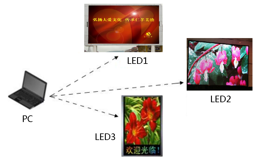
Effect diagram (Figure 01)
II, the hardware device
Required hardware equipment:
One computer;
Send a card;
Colorlight receiver card (T9, A8,5A here can be used as a controller card, for example, this article is 5A);
Gigabit Switch (optional)
III, the software settings
1, the configuration screen parameters
Separately for each piece of LED display parameter settings, save the parameter file LED1.rcvp;. LED2 rcvp;
LED3. Rcvp. (Specific parameter setting procedure, refer to "5A receiver card commissioning steps")
2, set the number of screens
Open the "Control Screen" → "Screen Management" to enter the screen management interface, set the number of screens to "1." At this time,
Software is only a LED screen.
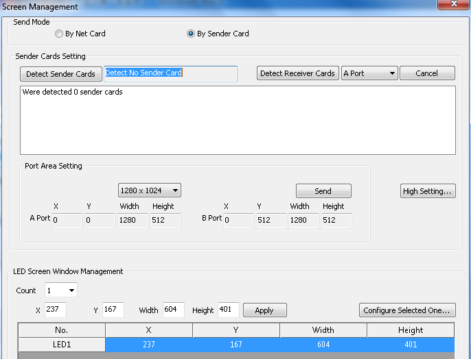
Set interface (Figure 02)
3, the loading screen parameters
Send a copy of the card is used in desktop mode, you need three LED display in a different area, by receiving a card connection settings change each screen coordinates.
The computer and the first piece of the LED display with a net line directly connected, click on the software's "Screen Management" in the "Configuration select screen parameters", "password" 168 ", enter" receiving card parameter settings "screen, click" file Load "Load the first step to get the" LED1. rcvp ", and" Send to receive the card.
Click image to look Big Image
Loading parameters (Figure 03).
Disconnect the network cable, connect LED2, loading parameters, modify connection settings, right LED1 width, sent to the receiver card.
Click image to look Big Image
Connection settings (Figure 04)
Disconnect the network cable, connect LED3, loading parameters, modify connection settings, right LED1 and LED2 total width, sent to the receiver card.
Note: A. loading screen parameters of the process, the computer must be loaded with an LED display parameters are directly connected, other
LED display of the network cable must be disconnected.
IV, the hardware connection
Kalai Te control system software is set up, the hardware connection is quite flexible, customers can according to the construction site
The actual hardware connection environment, mainly in the following three options after the summary.
A. series
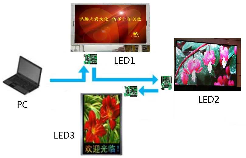
Serial diagram (Figure 05)
B. Parallel
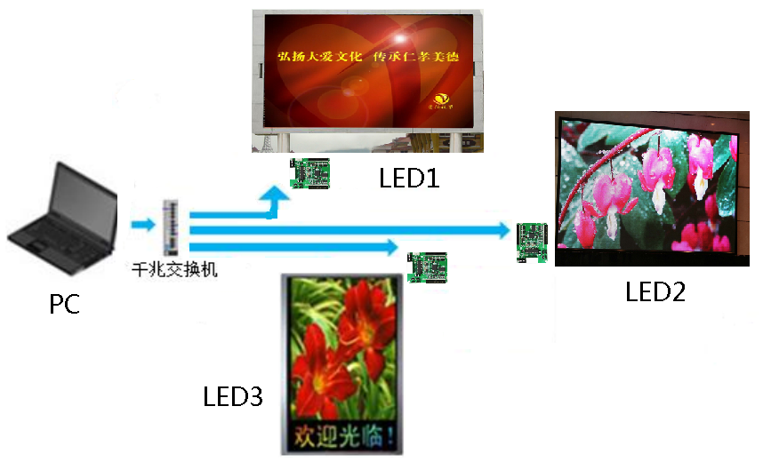
Parallel diagram (Figure 06)
C. Even mixed
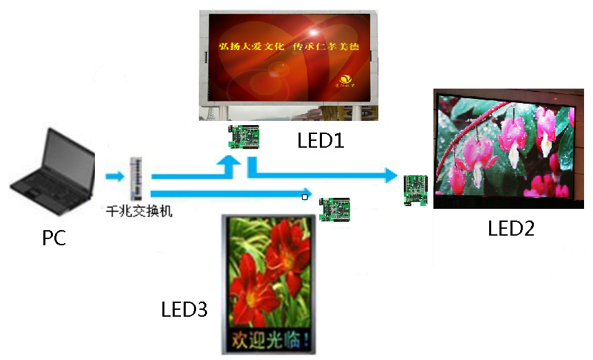
Even mixing diagram (Figure 07)
V、Edit the program
As long as players in the specified location corresponding program, the display will be able to display properly.
You can build an LED, add different program windows, you can create different LED tablecloth.

Contact: Lee
Phone: +86-132-6566-7728
E-mail: info@colorlitled.com
Add: Tangtou Industrial Park,Shiyan,Baoan,Shenzhen