CUSTOM SUPPORT & SALE
CUSTOM SUPPORT & SALE
Chapter
1. Settings of screen management interface
4. Settings of effect parameters
1. Settings of screen management interface
The software parameter settings are based on how the screen management interface has been set, so please be sure to confirm all aspects of the screen management are correct. Open the software LEDVISION, and click [Control Screen] → [Screen Management] to open the screen management interface (Figure 3-1). There are two options, namely, by net card and by sending.
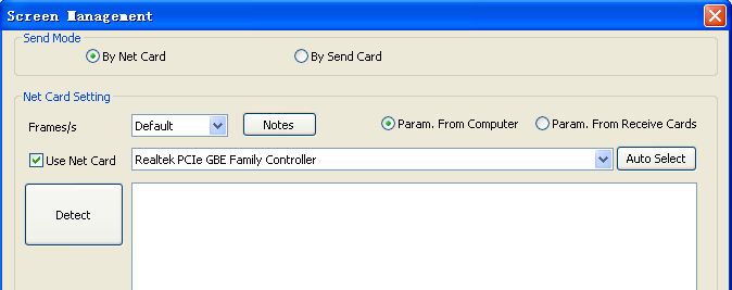
Figure 3-1 Screen Management Interface
By Net Card
Computer configuration: Gigabit Ethernet transmission card
The “By Net Card” interface is as shown in Figure 3-2.
Net card installation: Install a stand-alone Gigabit Ethernet transmission card in the computer PCI slot, and correctly set up the NIC driver (The computer integrated Gigabit Ethernet transmission card can also be accepted).
Net card selection: On the “By Net Card” interface, check “To Use Net Card” and then select the Gigabit Ethernet transmission card in the drop-down menu on the right, and if more than one card is shown, and you are not sure which one to choose, you can click “Automatically Selected”.
Detect receiving cards: Click [Detect Receiving cards], the system will prompt “A receiving card is detected, with the version number is ...” which means that the communication is normal and you can continue to set the parameters. If it prompts “No receiving card is detected”, you need to check whether the network cable is normal, or whether it is a gigabit network card and so on.
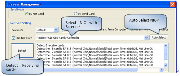
Figure 3-2 “By Net Card” Interface
By Sending
Computer configuration: stand-alone graphics card with DVI output, sending, serial and DVI cables as shown in Figure 3-3.
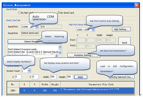
Figure 3-3 “By Sending” Interface
Serial port options: The serial ports are used to transmit control signals, and after the sending cards are connected to the serial cables and the serial port driver has been installed (automatically installed when the player software is being installed), it will automatically select the serial port after the software is opened.
Receiving card detection - used to detect whether the receiving card can provide normal communications (or observe whether the receiving card has its green light flashing). If no receiving card is detected, please check whether the receiving card is normally powered or whether the network cables are well contacted.
Net port control area settings: According to the size of the actual screen, select the net port control area as shown in Figure 3-4 (a), and then deliver to the sending. If the screen is relatively large and dual net ports are needed, you can use a custom mode, for example, display (1344 * 672), set the net port as shown in Figure 3-4 (b), and then deliver to the sending.

Figure 3-4 Net Port Control Area Settings
Sending resolution setting: The sending has its default resolution of 1280x1024, version 9.9 can support self-adaptive resolution, click on [Resolution Settings], and you can set the current display resolution, or customize the resolution (which the display can support) as shown in Figure 3-5. After set, it will prompt to cut off power, re-power the sending, and then set the copy mode.
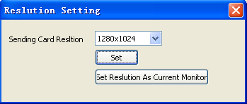
3-5 Sending Card Resolution Settings
LED screen size and area: The column length and row height here refers to the pixels to set the screen width and height, and the screen size is set to achieve full-screen display of the programs played via the software.
Click [Configure the selected one], enter the password “168” in the Password box to display the interface for settings of the receiving card parameters as shown in Figure 3-6.
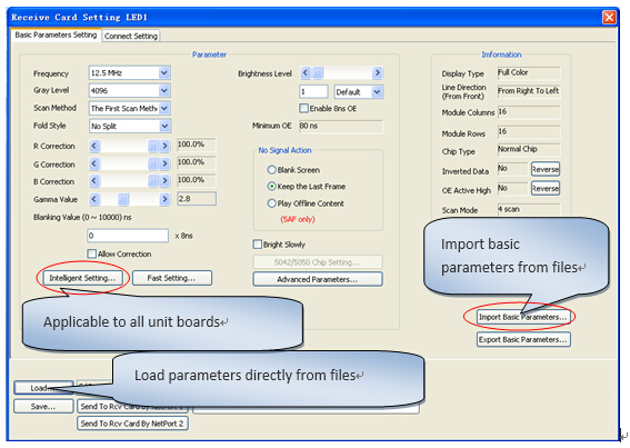
Figure 3-6 Interface for Receiving card Parameters Setting
1). Load the correct configuration files.
Our software has provided parameters of conventional unit boards, so you can select and load appropriate parameters according to the types of your unit boards (for example, full-color real or virtual scan mode). If no proper display, click “Next” or directly load the parameters the screen has saved before. (You can directly pass this step, too.)
2). Import and export basic parameters
After the unit board debugging has been completed, you can export the basic parameters, and when commissioning the entire screen parameters, you can directly import the basic parameters. (You can directly pass this step, too.)
3) Complete parameters setting via intelligent setting
Intelligent settings can identify the scan number and the scan line modes of all modules, and easily manage the settings of all unit boards.
Wizard 1: Select the correct display type, including full-color real pixel and full-color virtual (virtual screens should adopt virtual pixel arrangement). Then, enter the number of columns in a single module, as shown in Figure 3-7.
Driver IC type: regular or special IC chips (MBI5042, MBI5050, and a variety of lighting chips).
Sorting order: Select the cascading direction of the module, and view the data from the screen front - from right to left, left to right, top to bottom and bottom to top.
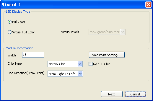
Figure 3-7 Intelligent Settings Wizard 1
The display panel has no 138 chip: It is applicable to such driver panels without 138 decoding chips. This option supports the cases of 1 / 2 and 1 / 4 scanning. (Note that this option shall not be selected for static modules.)
Wizard 2: Observe the display screen and select the correct display status.
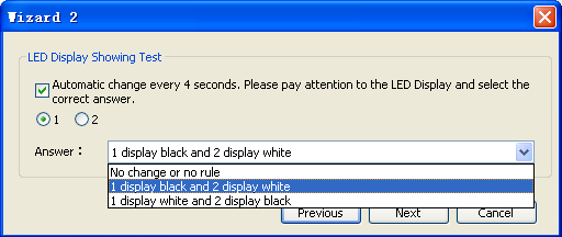
Figure 3-8 Intelligent Settings Wizard 2
Wizard 3: Observe the display screen and select the correct OE signals.
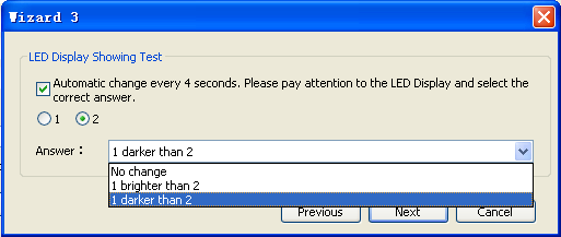
Figure 3-9 Intelligent Settings Wizard 3
Wizard 4: Observe the display screen and identify the correct color.
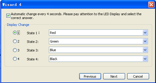
Figure 3-10 Intelligent Settings Wizard 4
Wizard 5: Observe how many rows are light on the first module of the display screen (to determine how many rows a set of data can control).
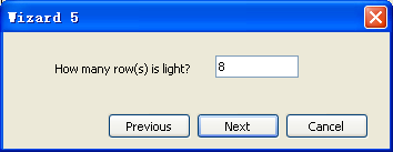
Figure 3-11 Intelligent Settings Wizard 5
Wizard 6: Observe how many rows are light on the first module of the display screen (to determine the scan mode).
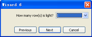
Figure 3-12 Intelligent Settings Wizard 6
Wizard 7: Highlight points (if the whole display screen is connected for intelligent settings, only observe the first module connected to the first FPC of the receiving card).
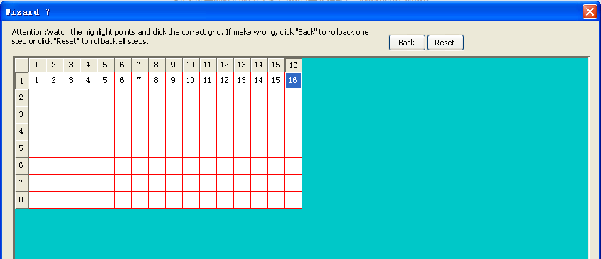
Figure 3-13 Intelligent Settings Wizard 7
In “Receiving card Connection”, you can set the control area of each receiving card. For standard display screens, the connection settings can follow the steps as shown in Figure 3-14.
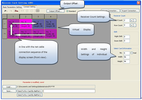
Figure 3-14 Interfaces for Connection Settings of Receiving Card
Setting steps:
(1) Set receiving card rows and columns: namely, the rows and columns for arrangement of the receiving card on the display screen. For example: 2 rows, 4 columns.
(2) In the receiving card rows and columns of [Virtual Display Window], select the position of the first card (which is directly connected to the sending), and in the [Selected Card Information] area, set its width and height, for example, width: 96, height: 96.
Click the position of each card in order according the actual connection order of the receiving card (as the white arrows show in the figure), and the software will automatically configure the relevant parameters by default automatically based on the settings of the previous card.
(3) If all receiving cards are different in area, you can only select the receiving card to be modified and manually modify the parameters of the single receiving card.
(4) The data port offset is designed for special-shaped display screens (you can skip such setting for standard display screens). The special-shaped display screens as shown in Figure 3-15 can be set as shown in Figure 3-16:

Figure 3-15

Figure 3-16
4. Settings of effect parameters
A. Parameters setting: Users can set such different parameters as serial frequency, gray level and brightness level by the drop-down button slider, with the parameter interface as shown in Figure 3-17.
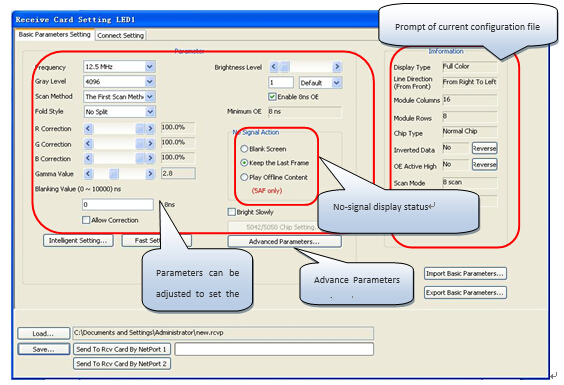
Figure 3-17 Interface for Receiving card Parameters
Serial frequency: It refers to the serial clock frequency to control the driver chip on the display panel, with the maximum of 41.7MHz. (If the serial frequency increases, the gray level, brightness level, refresh rate and other parameters may be appropriately up to higher values, the maximum serial frequency is subject to the display panel wiring and driver chips, and full-color screens generally use 17.9MHz).
Gray levels: You can freely adjust the gray levels from zero to 65,536. In general, indoor full-color screens use 2,048 or 4,096 levels of gray. Outdoor static full-color screens use the gray level of 4,096 or 8,192.
Scan modes: Scan mode 1 means to scan the gray level first and then rows, and as a routine scan mode of display screens, it is specially recommend to customers; Scan mode 2 means to scan the rows first and then the gray levels, featuring eight times more refresh rate than the normal mode, and able to meet customers’ requirements for a higher refresh rate, but some display screens may have dark dots appearing.
Double-up mode: The double-up free mode can be selected for general display screens. As for co-double-up and counter-double-up, the software can support 1-8 groups of data as conventional output, and 9-16 groups of data as co-double-up and counter-double-up output. As for co-double-up in half, the software can support 1-4 groups of data as conventional output, and 6-16 groups of data as co-double-up output in half. (The double-up method is generally used in conjunction with the data exchange)
Red, green and blue correction: Each color can be separately adjusted to fine-tune the color channel offset. Slight adjustment will have no harm to the gray-scale effect.
Gamma value: Gamma value will affect the display effects, so it is a key parameter of LED display. Gamma is usually set between 2.2 to 2.8. Smaller Gamma value can ensure that a lower gray level be expressed. However, bigger Gamma value can ensure that cascading effects be achieved between gray levels. The software can also support manual adjustment of Gamma values. The Gamma value will also affect the gray value, and the smaller Gamma value, the smaller gray value. For example: in case of 4,096 gray levels, when Gamma is 2.2, the gray value should be 6; when Gamma is 2.8, the gray value should be 14.
Blanking value: When the screen has such phenomena as dark light and tailing, the blanking value can be appropriately increased.
Brightness levels: There are two kinds of settings:
I: Not enable 8ns OE: The OE changes to the minimum interval of 40ns, which is suitable for the majority of display screens.
II: Enable 8ns OE: The OE can be reduced to the minimum of 8ns to control OE more precisely, and appropriate decrease of the OE value can effectively improve the refresh rate.
Power-on fade-in: When the power is started, the screen will fade in for protection.
B. High parameters
Click [High Parameters] to open the “High Setting” interface as shown in Figure 3-18:
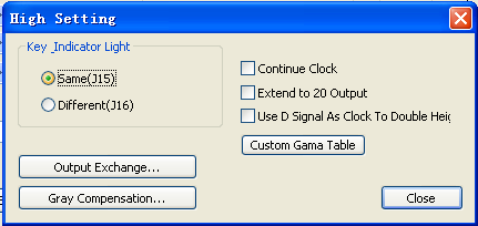
Figure 3-18
I: Continuous clock: Uninterrupted clock signals will be sent, which is applicable to the modules with HC123 chip protection circuit.
II: Extended to 20 sets of data: The receiving card can have its 16 sets of data extended to 20 sets.
III: Use D signals as clock extension height: Use the D signals as clock extension, so that the receiving card can have its 16 sets of data extended to 32 sets.
IV: Data exchange: As shown below, 16 groups of full-color data can be exchanged freely.

Figure 3-19
Ⅴ: Gray compensation: In case of bad low-gray effects, each gray level can be compensated separately.
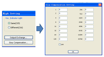
Figure 3-20
C. Information prompt: It will prompt the content information of the current configuration files, where “RP Data” and “OE High Efficiency” can be manually set and inverted.
Refresh rate: The software will automatically calculate the refresh rate according to the control area and associated parameters of the receiving card. Different from direct setting of the refresh rate, this refresh rate is accurate.
The refresh rate needs to be adjusted subject to adjustment of other parameters, with the relationship between the refresh rate and other parameters listed in the following table for reference.
|
Parameter Values |
Refresh Rate |
|
Serial frequency |
The higher serial frequency, the higher refresh rate |
|
Gray level |
The higher gray level, the lower refresh rate |
|
Brightness level |
The higher brightness level, the lower refresh rate |
|
Single card on-load length |
The longer single card on-load width, the lower refresh rate |
Minimum OE: When the minimum OE value is smaller, the screen will have worse gray effects. It is recommended that the minimum OE value be higher than 24ns, which can be changed by adjusting the brightness level.
C. No signal actions: According to the actual needs, it can be set as a black screen to retain the last frame image or play offline contents (For 5AF dual-mode systems, “Play Offline Contents” shall be selected for asynchronous use.)
After the display parameters have been set and the display is normal, you can directly send the parameters to the receiving card to save as a file (so that such parameters could be directly loaded later on.)
Special attention:
When a sending with a large screen (using two net ports) is adopted, you need to send the parameters of the two ports separately. For example: The display screen (1344 * 672) has 98 cards (W 14 × H 7), with the individual card on-load area of (96 * 96).
A. Net port 1 on-load area is (1344 * 384), with the connection settings as shown in Figure 3-21, and then select “Send to Receiving card by Net Port 1”;
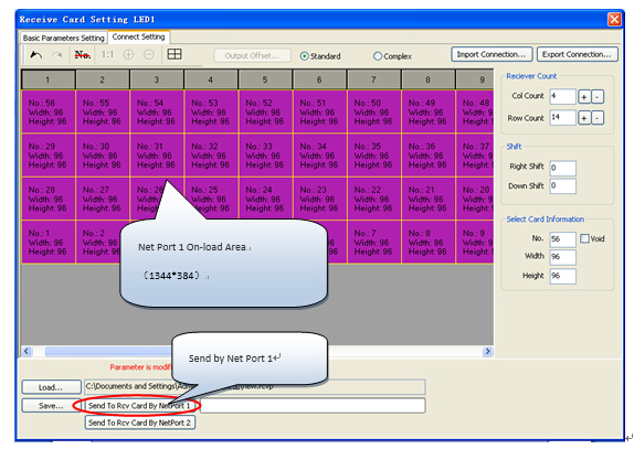
Figure 3-21 Connection Settings of Net Port 1 On-load Area
B Net port 2 on-load area is (1344 * 288), with the connection settings as shown in Figure 3-22, and then select “Send to Receiving card by Net Port 2”;
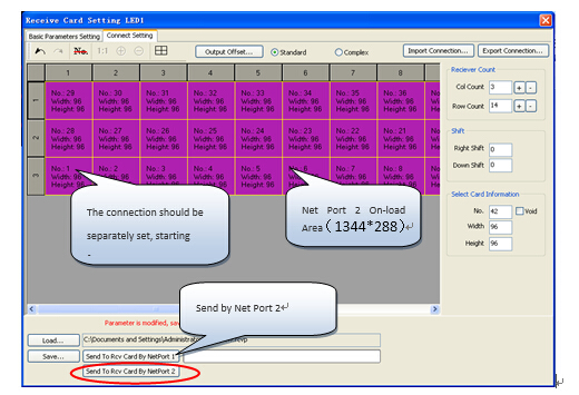
Figure 3-22 Connection Settings of Net Port 2 On-load Area
This step is only special for those display screens with parameters well adjusted but connections confused, and it is quite suitable for rented display screens or those display screens with relevant parameters well adjusted by the company. The detailed operations are as follows:
(1) Open the software, click [Control Screen] → [Config Selected One…], and enter the password “168” to open the interface for receiving card parameter settings (as shown in Figure 3-23)
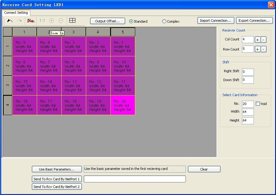
Figure 3-23 Send Connection Settings
(2) Set receiving card rows and columns: namely, the rows and columns for arrangement of the receiving card on the display screen. For example: 4 rows, 5 columns.
(3) Select the first card, set the on-load width and height of an individual card, and then set the serial number of the receiving card according to the physical connection order of the display receiving card (While sending connection diagrams, you should use the basic parameters saved in the first card rather than the software parameters, so to send a connection diagram will only change the connection order of the receiving card, but not disrupt the display parameters);
(4) Send to the receiving card (While sending, please pay attention to selection of Net Port 1 and Net Port 2).
Contact: Lee
Phone: +86-132-6566-7728
E-mail: info@colorlitled.com
Add: Tangtou Industrial Park,Shiyan,Baoan,Shenzhen