CUSTOM SUPPORT & SALE
CUSTOM SUPPORT & SALE
Chapter
1 5A and 5AF hardware figure and parameters
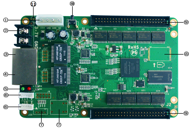
1.2 Hardware interface descriptions
2 5AS hardware figure and parameters
2.2 Hardware interface descriptions
1 5A and 5AF hardware figure and parameters

1.2 Hardware interface descriptions
|
S/N |
Name |
Function |
Remarks |
|
1 |
Power-in 1 |
Connect DC5V power supply to power the receiving card. |
Only one is used.
|
|
2 |
Power-in 2 |
Connect DC5V power supply to power the receiving card. |
|
|
3 |
Net port A |
RJ45, for transmission of network signals |
The dual net ports can achieve import/export at random, which can be identified in an intelligent way by the system. |
|
4 |
Net port B |
RJ45, for transmission of network signals |
|
|
5 |
Indicator light |
It indicates the status of power and signal transmission. |
Red for power, green for signals |
|
6 |
Peripheral ports |
For Indicator light and test buttons |
Two kinds of interface definitions |
|
7 |
Relay port |
The cabinet fan power can be controlled through the relay. |
To be customized |
|
8 |
Flash |
2Gbit memory chips can be soldered to store offline contents |
5AF version |
|
9 |
Dual 50P pins |
Connected to all display HUB boards |
|
|
10 |
Test buttons |
The attached test procedures can achieve four kinds of monochrome display (red, green, blue and white), as well as horizontal, vertical and other display scan modes. |
|
|
11 |
Temperature sensor port |
Temperature probes can be soldered to detect the temperature of each card. |
To be customized |
1) Indicator Light functions
Red: ON for power available
Green: ON/OFF quick flash (about 5-10 times / second) indicates that the data signal transmission is normal.
2) Definitions of 50P pins
|
Full Color |
Function |
Note |
|
2, 4, 47, 49 |
VCC 5V |
Power |
|
1, 3, 5, 46, 48, 50 |
GND |
Ground |
|
10, 14, 18, 22, 26, 30, 34, 38 |
R |
Data signal |
|
8, 12, 16, 20, 24, 28, 32, 36 |
B |
|
|
9, 13, 17, 21, 25, 29, 33, 37 |
G |
|
|
7, 11, 15, 19, 23, 27, 31, 35 |
RP (red virtual pixel) |
|
|
45 |
OE |
Control signal |
|
43 |
LAT |
|
|
44 |
CLK |
|
|
42 |
A |
Scan signal |
|
41 |
B |
|
|
40 |
C |
|
|
39 |
D |
|
|
6 |
Expansion port |
|
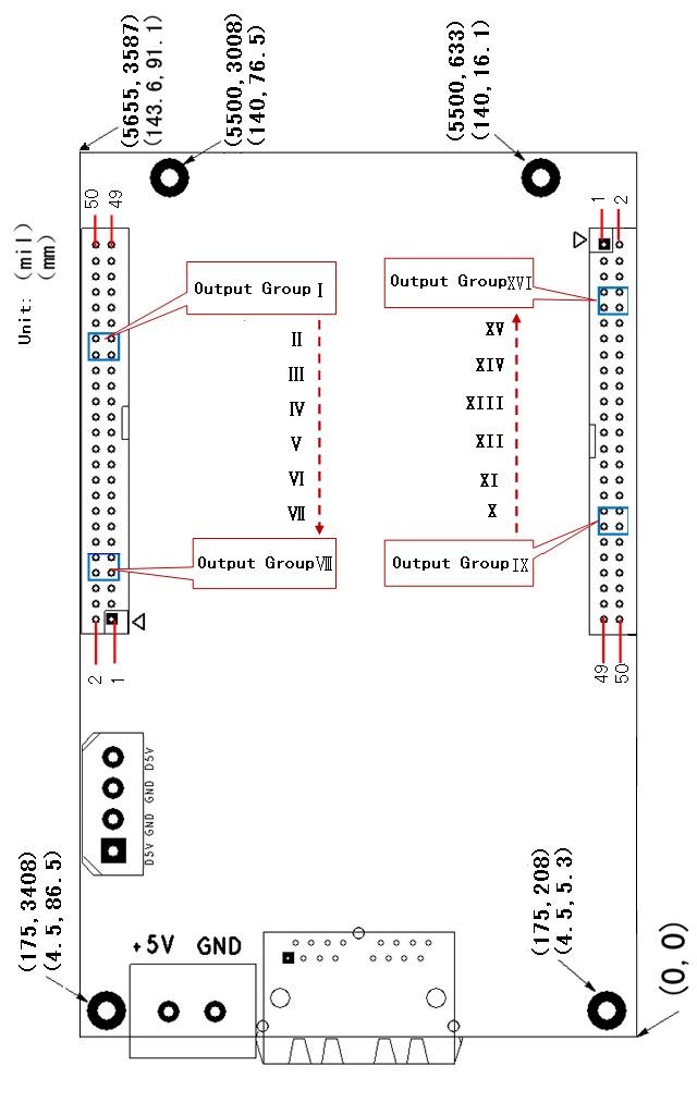
3) Figure for receiving card size and hole position

Figure 2-2
Voltage: 3-7V Current: 400-600mA
Power: 3W ± 5% Operating temperature: -25 ℃ - +70 ℃
2 5AS hardware figure and parameters

Figure 2 - 3
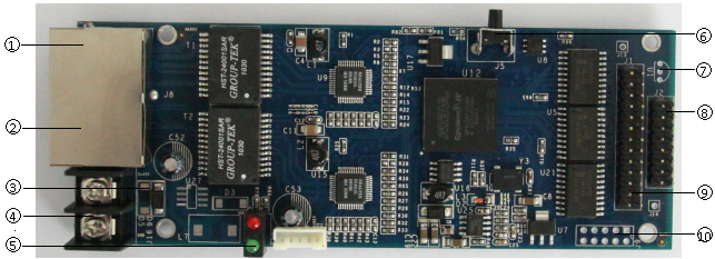
2.2 Hardware interface descriptions
|
S/N |
Name |
Function |
Remarks |
|
1 |
Net port A |
RJ45, for transmission of network signals |
The dual net ports can achieve import/export at random, which can be identified in an intelligent way by the system. |
|
2 |
Net port B |
RJ45, for transmission of network signals |
|
|
3 |
D5,D6 |
If D5 is welded but D6 not, the input voltage will be 6V ~ 45V, and if less than 6V, the system does not work; if D6 is welded but D5 not, the input voltage will be 5V, ± 10%, and if too high voltage, the system will be burned. |
Only one of the two shall be welded. |
|
4 |
Power-in |
To power the receiving card |
|
|
5 |
Indicator light |
It indicates the status of power and signal transmission. |
|
|
6 |
Test buttons |
The attached test procedures can achieve four kinds of monochrome display (red, green, blue and white), as well as horizontal, vertical and other display scan modes. |
|
|
7 |
Temperature sensor port |
Temperature probes can be soldered. |
|
|
8 |
Signal output port J2 |
Two groups of parallel RGB output or 6 groups of serial signals |
Only J1 or J2 is to be connected. |
|
9 |
Signal output port J1 |
Four groups of parallel data or 16 groups of serial output
|
|
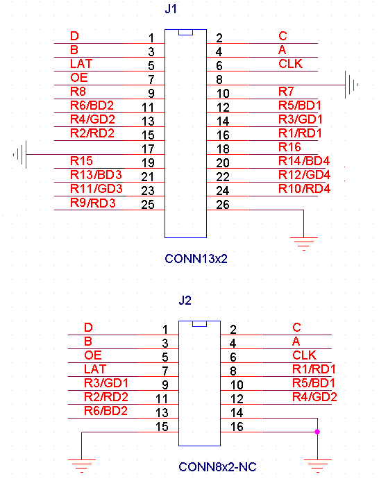
J1, J2 signal port definitions

Figure 2-4
Note: J1 and J2 can not be used together. J1 and J2 signals are defined as the first four and two groups of 5A cards respectively. Serial signals or signals in any other form can be achieved by updating the program.
Voltage: 5-45V Current: 400-600m
Power: 3W ± 5% Operating temperature: -25 ℃ - +70 ℃
Contact: Lee
Phone: +86-132-6566-7728
E-mail: info@colorlitled.com
Add: Tangtou Industrial Park,Shiyan,Baoan,Shenzhen